
Overview
ITQAN reworked an industrial load clamp that was designed to be milled on CNC machines. A design for manufacturing and cost review showed that producing it by milling would be too expensive for the client, especially for spares and low volumes.
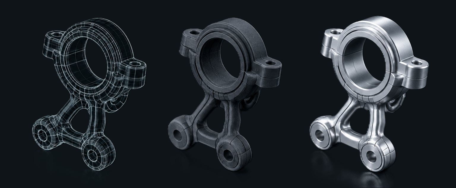
We redesigned the clamp for additive manufacturing in Autodesk Fusion 360. The optimized version is 40% lighter, at 0.288 kg against 0.480 kg, and in simulation it carries about 20% more load.
- Sector
- Manufacturing and automation
- Design Method
- Generative, automated modeling
- Software
- Autodesk Fusion 360
- Prototype
- FDM, PLA
- Production Specification
- Aluminum AlSi10Mg, DMLS
- Metal Printing
- Through our manufacturing partners
Explore the Model in 3D
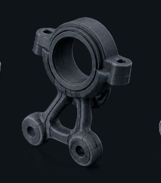
Drag to rotate, scroll or pinch to zoom. This is the optimized clamp geometry.
The Challenge: A Part Shaped by Its Cutter
The original clamp depended on 3-axis and 5-axis CNC milling. Milling needs clear paths for the tool, fairly regular geometry, and a lot of material removed from a solid billet. That created three problems for this part.
- Material waste. More than 65% of the raw stock ended up as chips, which pushed material cost up.
- Stress concentrations. Cutter geometry leaves sharp internal corners and hard transitions. Under heavy torque these act as stress risers.
- Cost of spares. Custom clamping setups and machine time make small batches and replacements expensive for the customer.
A part can be perfectly functional and still be the wrong design for the way it has to be made.
Studying the Original Design
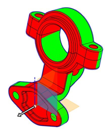
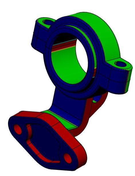
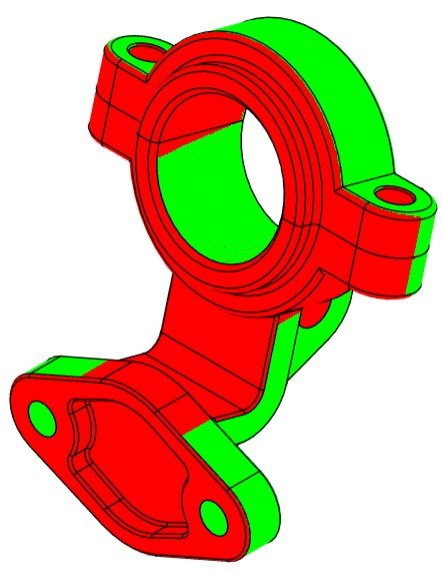
Before changing anything, we reviewed the original geometry for manufacturability. These colour-coded CAD views are from that analysis. They show where the original shape was shaped around tool access rather than around the loads it carries.
Our Approach: Keep the Interfaces, Rebuild Everything Between Them
In Autodesk Fusion 360 we kept only the geometry the clamp needs in order to work: the bolt-down surfaces, the pin bores and the clamp contact faces. The space between them was opened up as a design envelope.
We then applied static load cases that mirror real operation: the main clamping force, torsional loading and fastener preloads. An optimization algorithm removed material where stress was low and reinforced the main load paths.
The result is an organic web structure that spreads stress evenly across the body and reduces local stress peaks. It cannot be milled because of its internal undercuts and cavities, but it is well suited to being built layer by layer.
Checking It in the Real Assembly
Before committing to a production run, we printed both the original and the optimized clamp on an FDM printer in PLA and mounted them in the customer's assembly. This confirmed:
- Correct dimensional fit with the mating components and existing clearances.
- Technicians can reach the fasteners with their tools during assembly.
- The lighter geometry is easier to work with in the assembly.
Choosing the Production Material
With fit and form confirmed, the production specification moves from plastic to metal. We specified aluminum AlSi10Mg printed by direct metal laser sintering (DMLS), produced through our manufacturing partners. The reasons:
- Strength for its weight. An aluminum and silicon alloy that keeps the weight saving without giving up structural strength.
- Fatigue resistance. Load clamps see repeated loading and vibration, so resistance to fatigue under cyclic clamping matters.
- Suits fine geometry. The silicon content gives the melt pool good flow behavior, which helps reproduce the fine web features that toolpaths cannot reach.
- Responds to heat treatment. Standard thermal treatments such as T6-type aging can be used to balance ductility and raise strength toward the target performance.
Results
| Measure | Original Design | Optimized Design |
|---|---|---|
| Component mass | 0.480 kg | 0.288 kg (−40.1%) |
| Structural load capacity | Baseline | About +20% (estimated) |
| Manufacturing process | CNC milling | Metal additive manufacturing (DMLS) |
| Material waste | More than 65% of stock removed | Close to net shape |
| Cost of low-volume spares | High, due to setups and tooling | Lower, with no machining setups |
Mass figures come from the CAD models. The load capacity figure is an estimate from Fusion 360 simulation, not a test of a finished metal part.
What This Means for the Client
By replacing machining with optimization and additive manufacturing, the client avoids expensive machining setups altogether. Replacement and spare clamps become a printing job instead of a tooling job, and the part itself is lighter.
The same approach suits other legacy parts that are low in volume, carry real loads, and are currently machined from solid stock.
Next: the offset mounting bracket
Read the Bracket Study